| Note: | A typical Notion Lite installation would consist of a single Receiver (the Cloud Receiver, sometimes referred to as a Base Station) and three Transmitter-Sensors. For the Transmitter-Sensors, the procedure below (starting at Step 10) would need to be followed for each Transmitter-Sensor that you are using. |
See Equipment Positioning for guidelines on positioning and orienting the Notion Lite equipment.
Install Step |
Notes |
|---|---|
1.Using the mounting bracket as a drilling template, drill holes for the receiver wall mounting bracket into the wall at an appropriate location.
|
When mounting the Receiver, you should bear in mind that you will need to run cables from the receiver to a 12V power supply and to your Router.
|
2.Using the spacers provided to give clearance, screw the mounting bracket to the wall. |
|
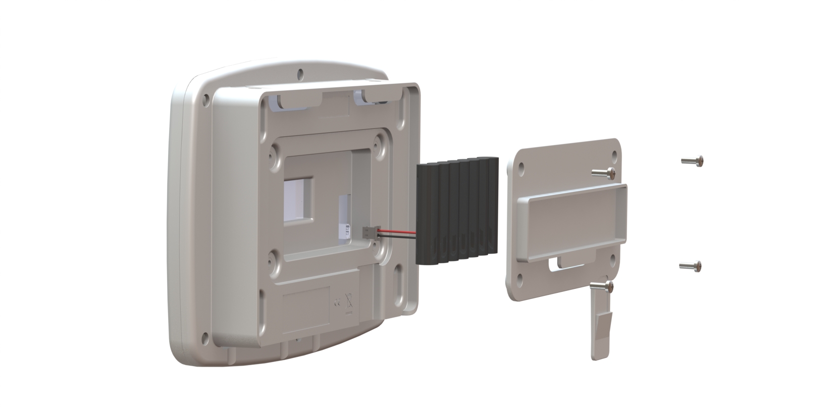
3.Using a Phillips screwdriver, remove and retain the screws from the battery cover plate at the rear of the Receiver. |
|
4.Insert the backup battery into the recess at the rear of the Receiver, taking care to insert the connector attached to the battery into the matching connector within the Receiver. |
|
5.Screw the battery cover plate to the rear of the Receiver. |
See also: |
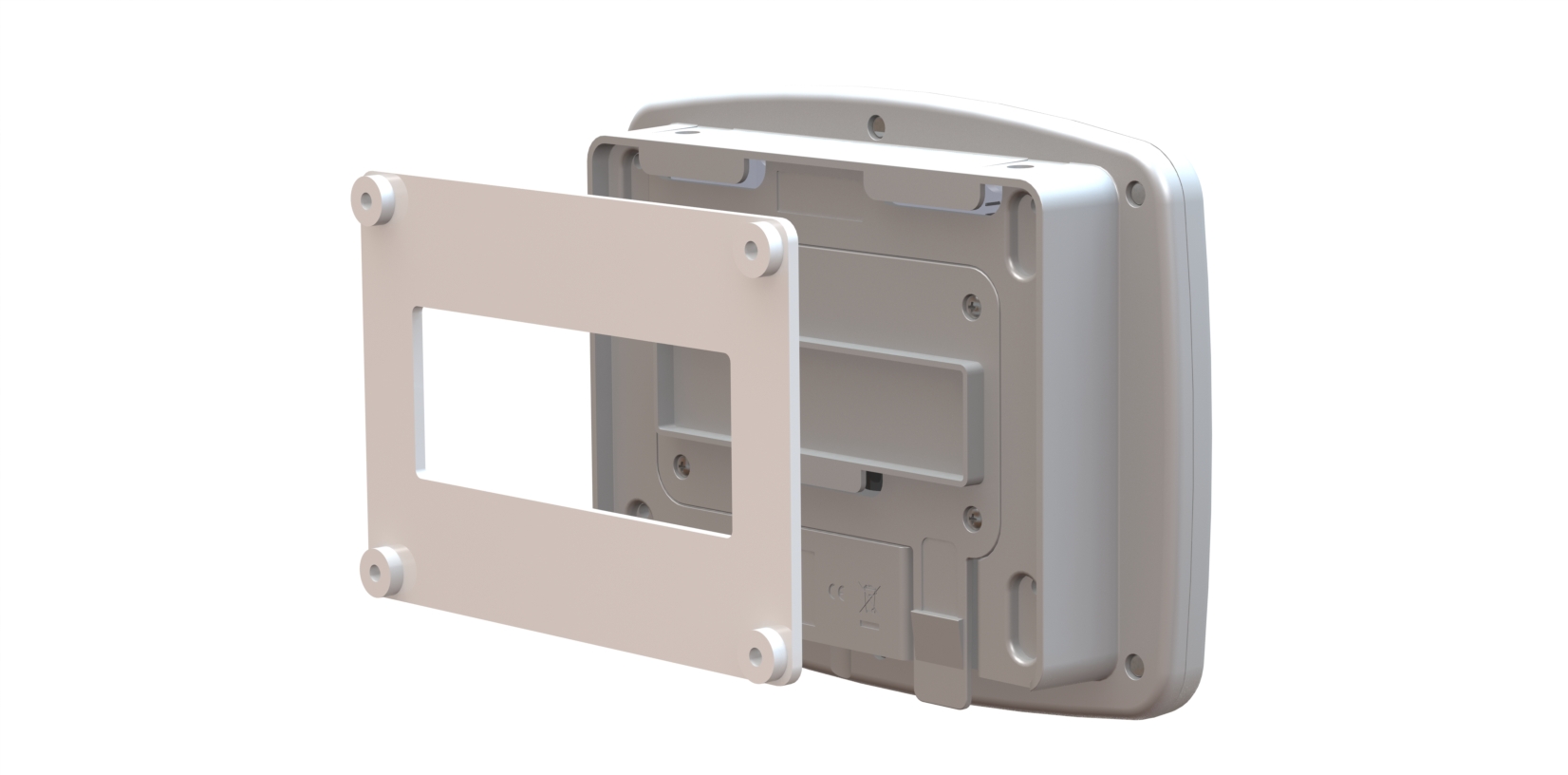
6.Attach the Receiver to the mounting bracket. |
Note: If you have not already registered your Receiver Unit you should do so before you wall-mount it. See Step 22 below. |
7.Using the supplied Ethernet cable, connect the Receiver to your Broadband Router or to a Network connection if you have one. |
|
8.Using the supplied cable, connect the Receiver to the 12V power supply. |
|
9.Slide the appropriate plug adapter onto the power supply. |
Do not connect the power supply to the mains supply yet. |
10.If you are NOT using the door switch option with this Transmitter-Sensor, go to step 11 below. Secure a matching pair of door switch sensor pads to the door and door frame of your refrigerated/frozen storage unit. |
•If you intend to the lay the Transmitter-Sensor loosely in the storage unit, ensure that you position the door frame sensor pad such that the cable running from the pad goes into the storage unit. •If you intend to wall-mount the Transmitter-Sensor, ensure that you position the door frame sensor pad such that the cable running from the pad runs outside of the storage unit. •Ensure that the pads meet perfectly when the door is closed. |
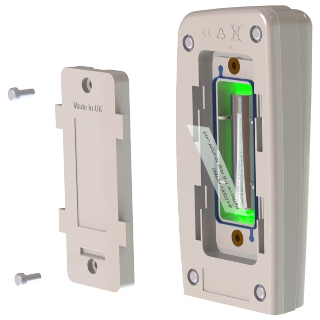
11.Pull away the contact tag on the Transmitter-Sensor to ensure the battery contacts and the Transmitter-Sensor contacts meet. |
A green flashing light comes on. This is normal and indicates that the Transmitter-Sensor has not been configured yet. See Configuring Transmitter-Sensors for details of how to set up the Transmitter-Sensors. The Transmitter-Sensors are powered by 1 x 1.5V Lithium AA cells. Standard AA cells can be used, but are not recommended. (1.5V Lithium AA batteries supplied with Transmitter-Sensor will work over range -30°C to +50°C. 1.5V AA alkaline can be used but will have reduced life and a reduced operating temperature range 0°C to +40°C.) See also Transmitter-Sensor Battery. |
12.If you DO NOT intend to wall-mount your Transmitter-Sensor, go to Step 20 below. |
(Transmitter-Sensor is lying loosely in your storage unit.) |
13.Drill holes for the Transmitter-Sensor wall mounting bracket into the wall at an appropriate location. |
Note that the mounting bracket may be delivered attached to the Transmitter-Sensor. Free the bracket by pulling downwards then outwards. When mounting the Transmitter-Sensor bracket, you should bear in mind that, if you are using the door switch and/or external sensor options, you will need to run cables from the Transmitter-Sensor to your storage unit door frame sensor pad and/or external sensor. |
14.Screw the mounting bracket to the wall. |
As an alternative, the Transmitter-Sensor bracket could be attached to a suitable post using cable ties. Slots are provided in the bracket for this purpose. |
15.Slot the Transmitter-Sensor onto the wall bracket. |
Note: If you have not already Registered your Transmitter-Sensor Unit you should do so before you wall-mount it. See Step 22 below.
|
16.If you are using the door switch option with this Transmitter-Sensor, route the storage unit door frame sensor pad cable up to the Transmitter-Sensor. |
|
17.If you are NOT using the external sensor option, go to Step 20. |
|
18.Place the external temperature probe and associated cable at a suitable position in your storage unit. |
|
19.Route the temperature probe cable over the door frame and up to the Transmitter-Sensor. Insert the cable into the Transmitter-Sensor. |
|
20.Repeat steps 10-19 above for each Transmitter-Sensor that you are using. |
|
21.Plug in the Cloud Receiver power supply to the mains supply and switch on at the mains socket. |
The green power LED comes on. See Receiver Start Up for more details of the Cloud Receiver start up sequence. |
22.Create your Account and Register your Receiver Unit and Transmitter-Sensors. |
Follow the online procedure at www.notionlite.com. |
23.Go into Notion Lite to set up your Transmitter-Sensors for use. |
See Configuring Transmitter-Sensors for details. |